January 19, 2013

December 30, 2012

TFT Touch Shield : Temperature And Timer

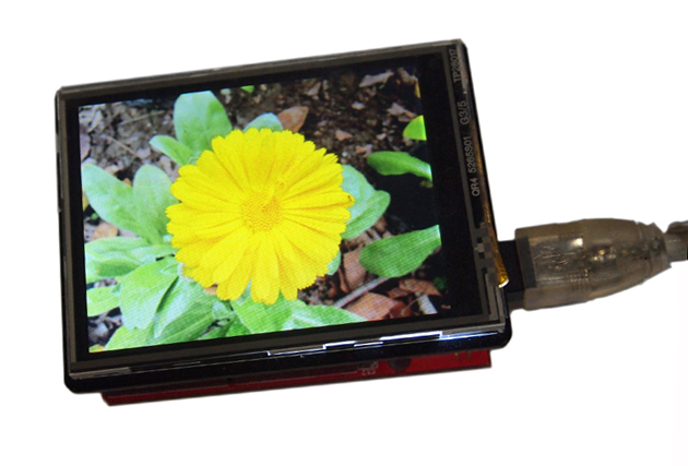
Instead of version 2.0 I've received the TFT Touch Shield Version 1.0 from Seeedstudio. This version doesn't have a SD-card and uses lots of pins for the communication. Version 2.0 instead uses the SPI protocol for communication. So, my blog post about SPI isn't necessary.

But this also simplifies the first version of my project:
  • display inside and outside temperatures
  • implement a timer with touch buttons

Temperature Measurement

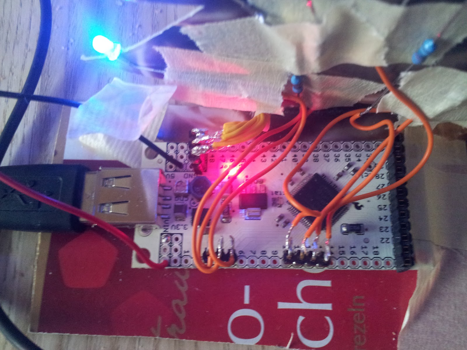
For the temperature measurement I'm using two DS18S20 temperature sensors from maxim integrated (see also my posting Temperature Sensors DS18B20). The TFT Touch Shield Version 1.0 uses nearly all pins from the Arduino board. Only analog pin A4 and A5 aren't used and those pins can be used as digital input pins. The DS18S20 temperature sensors are using the 1-wire interface and therefore only one pin is needed for the measurement.

The DS18S20 example code uses a delay(1000) which blocks the application and touch buttons of the timer. I've split the temperature measurement into two parts and the second part will be called after one second.

TFT and Touch Library

I've been using the TFT and Touch library which is mentioned in the Seeedstudio forum 2.8" TFT Shield Link : TFT_TouchScreen_for_Arduino_1.0.zip

This library is straight forward:

  • draw text with position, size and color
  • draw rectangles filled or not filled with position, width, height, and color
  • draw lines (not used at the moment)
  • and getting the touch position is also simple: just read the x and y position and it is also possible the get the z position for pressure. Depending on the position you can simulate a button (see timer).
The TFT Touch Shield isn't very fast (maybe Version 2.0 with an other chip is faster). You can see it when the TFT is drawing the items.
Drawing some text doesn't erase the previous text. Therefore the old text has to be overwritten overdrawn. For the temperature display I've been drawing a gray rectangle before the next temperature text is shown which results to a flickering view.
For the timer display I've reduced the flickering. I've been comparing each character from the old value with the new one and if it doesn't differ, I replace the values with a space. Therefore the old value isn't overwritten. Only those characters which differs has to be erased by a black color and drawn new.

The library also comes with a font. Each character is drawn by a 8x8 pixels. The text can have different sizes, but as bigger the size the more you can see the pixels (there's no anti-aliasing). Only ASCII characters from 0x20 (32dec) to 0x7e (126dec) are supported. This means umlauts aren't supported. 

Timer

For the timer I've been using a plus and minus sign to adjust the time by increases or decreases. Clicking on the time the timer starts to count down. To get the position and the button is very simple (as mentioned above). I've defined an area around the buttons and if the touch position is inside this area, the value changes or the timer starts. For the plus / minus button there's also a visual feedback by changing the color of the button in blue.

Source Code

... is available on github: https://github.com/choas/arduino-choas/tree/master/TftTouchTemperature

Next Version


This is my first simple version for a temperature display and timer. For the next version a temperature diagram would be nice to see the temperature changes during day and night. To switch between normal view and diagram view an image would be also nice.

I think version 2.0 of the TFT Touch Shield with a SD card simplifies this by reading an image and storing / reading the temperature data ...


December 28, 2012

SPI and Arduino

The TFT Touch Shield V2.0 (from Seeedstudio) uses the Serial Peripheral Interface SPI protocol. For Arduino a SPI library is available to communicate with SPI devices. Arduino is the master device.

Jeremy Blum explains the SPI interface in the Tutorial 8 for Arduino: SPI Interfaces:

Wikipedia has also something about the Serial Peripheral Interface Bus.

December 27, 2012

Temperature Sensors DS18B20

For my upcoming TFT Touch Shield project I've setup two DS18B20 temperature sensors. These sensors using the 1-wire interface which means that I just need one Arduino pin for those two sensors.

The first temperature sensor (sensor above in the image) is connected with VDD, DQ (Data In/Out) and GND. Between VDD and DQ there's a 4.7 kOhm resistor. The second one (sensor below in the image) is only connected by DQ and GND. This one is in parasite mode which takes the power from the DQ and therefore doesn't need an external power supply. The temperature sensor is a DS18B20+PAR which already connects internally Pin 1 (GND) and Pin 3 (VDD).


This is the Arduino Serial Monitor output using the OneWire example code:


    R=28 2A 4C 3C 4 0 0 6B Device is a DS18B20 family device.
    P=1 53 1 4B 46 7F FF D 10 E9  CRC=E9
    21.18
    R=28 C6 96 90 4 0 0 67 Device is a DS18B20 family device.
    P=1 51 1 4B 46 7F FF F 10 FE  CRC=FE
    21.06

Every DS18B20 temperature sensor has a unique ID. 28 C6 96 90 4 0 0 67 is use by the DS18B20+ and 28 2A 4C 3C 4 0 0 6B is the ID for the DS18B20+ PAR sensor.


I've been using the parasite temperature sensor as outdoor sensor. Therefore I only need two wires for GND and DQ. And this is the temperature curve when I made the temperature sensor with a glue gun water resistant:
Thanks to maxim integrated for the samples. I think I would never tested the DS18B20+PAR.

December 22, 2012

In The Meantime : IOIO XMas Tree

While I'm waiting for the TFT Touch Shield (a December give-away from Seeedstudio) to start the next project, I've build a programmable XMas Tree with an Android phone and a IOIO board.

This is the XMas Tree in action (photo by +Aygul Zagidullina at the Nerdmare Before Christmas event):

IOIO (pronounced: yo-yo) is a product which lets you connect electronic circuits to an Android device and control them from an Android application. [1]

I've connected pin 3, 4, 5, and 10, 11, 12, 13 with seven 120 Ohm resistors and blue LEDs. For a detailed description of the pins take a look at Getting To Know The Board :

... and for the tree I've used a cardboard:

The IOIO Xmas Tree is programmed with an Android phone. For each light there's a toggle button, to turn the light on and off. The time which it takes to change the state is also recorded.


Programming the IOIO board is simple (if you're choosing useful pins middle in the night). In the setup method you define which pin is a digital output:

leds[i] = ioio_.openDigitalOutput(pins[i], true);

... and inside of the loop method you just write true or false to set 5V or 0V to the pin and therefore turn the light on or off:

leds[i].write(false);

Source code of the Android project is available on Github/choas/IOIOXMasTree.

December 10, 2012

Next Project : TFT Touch Shield

I'll receive the TFT Touch Shield V2.0, another monthly give-away from Seeed Studio.
The idea is to measure the outside and inside temperature and show these values on the TFT display. The TFT Touch Shield also have a SD card module integrated. So I could read an image from the SD card and use it as background image.

 ... and for the touch part a configuration menu allows to configure:
  • temperature display
    show inside, outside, none or both temperatures, a temperature graph (stored temperatures from the SD card)
  • background image
    choose between an image, a random image, temperature dependent image, none, or just a color
  • timer
    select the minutes and start the timer 
  • display
    always on or turn off after x minutes (therefore a capacitive sensor will turn the display on)

For the temperature measurement I'm not sure, if I'm using
  • a SPI one from TI, because the TFT Touch Shield communicates via SPI protocol
  • a DS18S20 with a 1-Wire bus from Dallas/Maxim (mentioned by Enrico Sadlowski in the German Android Google+  Community)
  • or a simple temperature resistor
... but I've got some time before the TFT Touch Shield arrives.